Fall 2022 CS543/ECE549
Assignment 4: Single-view and two-view geometry
Due date: Tuesday, November 15, 11:59:59PM
The goal of this assignment is to perform single-view 3D measurements, fundamental matrix estimation, triangulation, and camera calibration.
Contents
- Part 1: Single-view geometry
- Part 2: Fundamental matrix estimation, camera calibration, triangulation
- Grading checklist and submission instructions
Part 1: Single-View Geometry
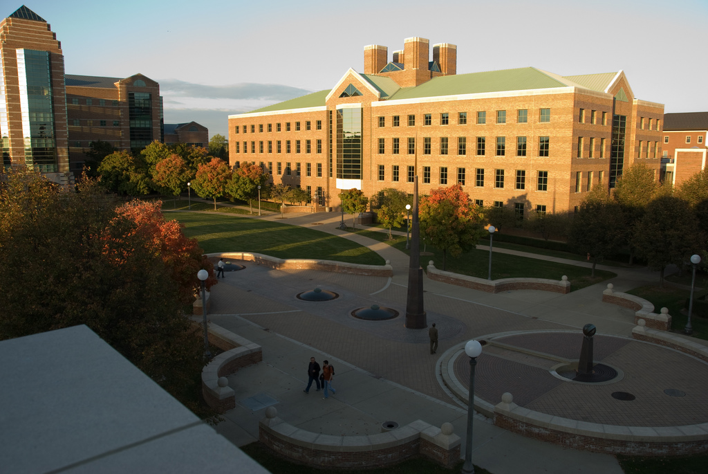
- You will be working with the above image of the North Quad (save it to get the full-resolution version). First, you need to estimate the three major orthogonal vanishing points. Use at least three manually selected lines to solve for each vanishing point.
The part 1 starter code provides an interface for selecting and
drawing the lines, but the code for computing the vanishing point needs to be inserted. For
details on estimating vanishing points, see Derek Hoiem's book chapter (section 4). You should also refer to this chapter and the single-view metrology lecture for details on the subsequent steps. In your report, you should:
- Plot the VPs and the lines used to estimate them on the image plane using the provided code.
- Specify the VP pixel coordinates.
- Plot the ground horizon line and specify its parameters in the form a * x + b * y + c = 0. Normalize the parameters so that: a^2 + b^2 = 1.
- Using the fact that the vanishing directions are orthogonal, solve for the focal length and optical center (principal point) of the camera. Show all your work.
- Compute the rotation matrix for the camera, setting the vertical vanishing point as
the Y-direction, the right-most vanishing point as the X-direction, and the left-most
vanishing point as the Z-direction.
- Estimate the heights of (a) the CSL building, (b) the spike statue, and (c) the lamp posts assuming that the person nearest to the spike is 5ft 6in tall. In the report, show all the lines and measurements used to perform the calculation. How do the answers change if you assume the person is 6ft tall?
Extra Credit
- Perform additional measurements on the image: which of the people visible are the tallest? What are the heights of the windows? etc.
- Attempt to fit lines to the image and estimate vanishing points automatically either using your own code or code found on the Web.
- Attempt to create a simple texture-mapped 3D model of the ground plane, CSL building, and the spike sculpture.
- Find or take other images with three prominently visible orthogonal vanishing points and demonstrate varions measurements on those images.
Part 2: Fundamental Matrix Estimation, Camera Calibration, Triangulation
You will be using these four image pairs:


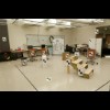
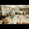
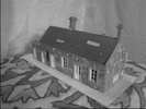


First, download the full-size images and data files and part 2 starter code. Note, the images shown above are just thumbnails and should not be used directly. Also note that the house and gaudi pairs are only to be used for item 5 below.
- Fundamental matrix estimation from ground truth matches. Load the lab and library image pairs and matching points file using the starter code. Add your own code to fit a fundamental matrix to the matching points and use the sample code to visualize the results. You need to implement and compare the normalized and the unnormalized algorithms (see this lecture for the methods). For each algorithm and each image pair, report your residual, or the mean squared distance in pixels between points in both images and the corresponding epipolar lines.
- Camera calibration. For the lab pair, calculate the camera projection matrices by using 2D matches in both views and 3-D point coordinates given in lab_3d.txt in the data file. Refer to this lecture for the calibration method. Once you have computed your projection matrices, you can evaluate them using the evaluate_points function included in the starter code, which will provide you the projected 2-D points and residual error. (Hint: For a quick check to make sure you are on the right track, empirically this residual error should be < 20 and the squared distance of your projected 2-D points from actual 2-D points should be < 4.)
For the library pair, there are no ground truth 3D points. Instead, camera projection matrices are already provided in library1_camera.txt and library2_camera.txt.
- Calculate the camera centers for the lab and library pairs using the estimated or provided projection matrices.
- Triangulation. For the lab and library pairs, use linear least squares
to triangulate the 3D position of each matching pair of 2D points given the two camera projection matrices
(see this lecture for the method). As a sanity check, your triangulated 3D points for the lab pair should match very closely the originally provided 3D points in lab_3d.txt.
For each pair, display the two camera centers and reconstructed points in 3D. Also report the residuals
between the observed 2D points and the projected 3D points in the two images.
- Fundamental matrix estimation without ground-truth matches.
The provided house and gaudi image pairs do not include ground truth 2D matches. For these pairs, you will use your putative match generation and RANSAC code from Assignment 3 to estimate fundamental matrices.
To generate matches, you should use the SIFT descriptor functions from OpenCV mentioned in Assignment 3.
For this part, only use the normalized algorithm. Report the number of inliers and the average residual for the inliers, and display the inliers in each image.
Tips and Details
- For fundamental matrix estimation, don't forget to enforce the rank-2 constraint.
This can be done by taking the SVD of F, setting the smallest
singular value to zero, and recomputing F.
- Recall that the camera centers are
given by the null spaces of the matrices. They can be found by taking the SVD of the
camera matrix and taking the last column of V.
- You do not need the camera centers to solve the triangulation problem. They are used just for the visualization.
Extra Credit
- Perform nonlinear refinement of esimated fundamental matrices and/or triangulated points by minimizing pixel-level residuals as explained in the lectures.
- Estimate the fundamental matrix using the seven-point algorithm.
Grading checklist
Be sure to include the following in your report:- Single-view geometry: See items 1-4 in Part 3 above.
- Fundamental matrix estimation, calibration, triangulation:
- For the lab and library image pairs, display your result (points and epipolar lines) and report your residual for both unnormalized and normalized fundamental matrix estimation.
- For the lab image pair, show your estimated 3x4 camera projection matrices. Report the residual between the projected and observed 2D points.
- For the lab and library image pairs, visualize 3D camera centers and triangulated 3D points.
- For the house and gaudi image pairs, display your result and report your number of inliers and average inlier residual for normalized estimation without ground truth matches.
Submission Instructions
You must upload the following files on Canvas:
- Your code in two separate files for part 1 and part 2. The filenames should be lastname_firstname_a4_p1.ipynb and lastname_firstname_a4_p2.py. For part 1, you should also output an exported PDF of the notebook as lastname_firstname_a4_p1.pdf (do the same for part 2 if you decide to submit your code as a Python notebook).
- A report in a single PDF file with all your results and discussion for both parts following this template. The filename should be lastname_firstname_a4.pdf.
- All your output images and visualizations in a single zip file. The filename should be lastname_firstname_a4.zip. Note that this zip file is for backup documentation only, in case we cannot see the images in your PDF report clearly enough. You will not receive credit for any output images that are part of the zip file but are not shown (in some form) in the report PDF.
Please refer to course policies on late submission, academic integrity, etc.